
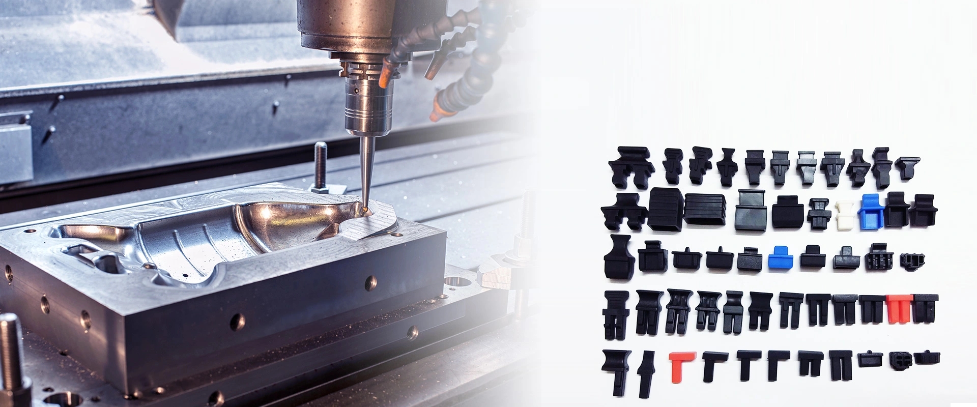

Product Center
The OSFP (Octal Small Form Factor Pluggable) specification is developed by the OSFP MSA. It specifies mechanical, electrical, thermal management and optical interface requirements for 8-lane pluggable optical transceivers, mating connectors and host cages, with management interfaces complying with the CMIS standard. This specification facilitates data center bandwidth migration from 400G to 800G and beyond.
Mechanical Specifications
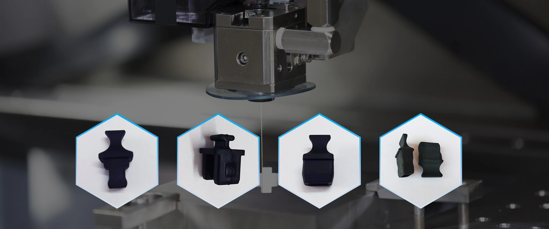
OSFP transceivers are available in three front-profile form factors: Type 1, Type 2 and Type 3 while retaining identical main body width. Either enclosed or open-style heatsinks can be assembled on the module front end, and optional cooling fins may be fitted on the bottom side. The internal PCB adopts a double-row 60-contact edge connector, delivering 8 differential transmit pairs and 8 differential receive pairs for high-speed signals. Contacts feature a three-step staggered length design to enforce a mating sequence: ground first, power second, signal last. Latch pockets and release mechanisms are integrated on both module sides for secure locking onto host cages. Different pull-tab colors denote distinct product applications, e.g., black for copper cable variants, beige for SR8, and green for FR4.
Cage and Connector
The standard specifies multiple cage and connector constructions including single-row SMT, stacked SMT and press-fit stacked configurations. Equipped with EMI springs, polarization keys, stop shoulders and ventilation openings, cages support multi-port layouts such as 1×1, 1×4, 2×1 and 2×4. Detailed dimensional requirements cover front panel cutouts and PCB layouts including back-to-back mounting. Unoccupied ports must be plugged with dummy inserts to suppress EMI leakage and regulate airflow.
Electrical Interface
The 60-position connector consists of 8 TX differential pairs, 8 RX differential pairs, 4 VCC power pins with a maximum aggregated current of 10 A (supporting over 30 W power delivery), 20 ground pins, plus low-speed control lines including SCL/SDA, INT/RSTn and LPWn/PRSn. Multi-level bidirectional circuitry is deployed on low-speed signals to implement module presence detection, low-power mode, interrupt and hardware reset functions. High-speed lanes support multiple electrical interface standards: 800GAUI‑8 (112 G PAM4, 8×100 Gb/s), 400GAUI‑8 (56 G PAM4, 8×50 Gb/s) and dual CAUI‑4 (25 G NRZ, 8×25 Gb/s), enabling a maximum aggregate bandwidth of 800 Gb/s. Eight power classes (Class 1 through Class 8) are defined: power consumption is limited to ≤2 W under low-power mode, while high-power options range from 1.5 W up to above 14 W for Class 8. Optional power filtering and electronic circuit breakers safeguard hot-plug reliability.
Thermal Performance
Multiple case temperature grades are defined: commercial (0 °C to 70 °C), extended industrial (-5 °C to 85 °C) and full industrial (-40 °C to 85 °C). In accordance with EIA‑364‑70, connectors are qualified for a 10‑year service life with a maximum temperature rise ≤30 °C at 65 °C ambient. Airflow impedance curves are characterized via dedicated test fixtures to guide thermal design optimization.
Optical Interface
A comprehensive range of optical receptacles is supported: duplex LC, MPO‑12, MPO‑16, dual-row MPO‑12, MXC, dual Mini‑LC, dual LC, dual CS, quad MDC, quad SN, dual MPO, dual MXC, 8×MDC and 8×SN. PMD block diagrams and lane-to-fiber mapping are defined for mainstream 400G PMDs (DR4, SR8, FR4, FR8/LR8 etc.) and 800G PMDs (DR8, BD4.2, 2×FR4, FR4, FR8/LR8, SR8 etc.).
Reliability & ESD Compliance
Durability criteria require 50 mating cycles for pluggable modules and 100 cycles for mating connectors and cages. ESD performance meets EN61000‑4‑2 (8 kV contact discharge, 15 kV air discharge) and 1000 V HBM specifications.
Summary
OSFP Revision 4.1 establishes a complete hardware specification for 400G/800G pluggable transceivers and serves as a core foundational standard for next-generation data center interconnection.
快速链接
如有任何疑问,请通过电子邮件或Skype联系我们,我们会尽快回复您。
e-mail:sw@2011sw.com
Skype:s13356471172
微信:13356471172