

Product Center
Developed by the QSFP MSA, this specification defines electrical, mechanical, thermal and management interfaces for the first-generation QSFP (Quad Small Formfactor Pluggable) 4-lane pluggable optical transceivers. It delivers a high-density, low-power module solution compatible with Ethernet, Fibre Channel, InfiniBand and other industry protocols.
Electrical Interface
The QSFP transceiver features a 38-position edge connector with 19 pads per side, accommodating four differential high-speed transmit/receive pairs (Tx1~Tx4, Rx1~Rx4). Low-speed control signals comprise ModSelL (Module Select), ResetL (Hardware Reset), LPMode (Low-Power Mode), ModPrsL (Module Present Indicator) and IntL (Interrupt).
High-speed differential links are specified for 100 Ω AC-coupled impedance; receiver output swing ranges from 340 mVpp to 1600 mVpp while transmitter input swing spans 500 mVpp to 1600 mVpp. Receiver squelch is mandatory and optional transmitter squelch is defined.
Three power pins VccTx, VccRx and Vcc1 are implemented with a maximum rated current of 500 mA per contact. Four power classes are specified: Class1 (1.5 W), Class2 (2.0 W), Class3 (2.5 W) and Class4 (3.5 W). Modules default to low-power mode after power-up (logic-high LPMode), capped at 1.5 W power consumption with only the 2-wire serial bus and laser safety circuits active.
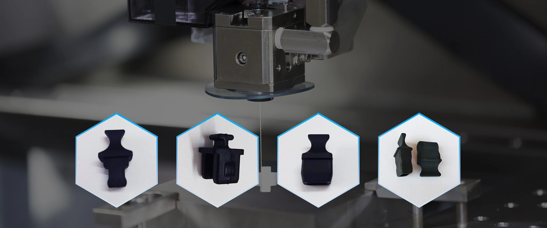
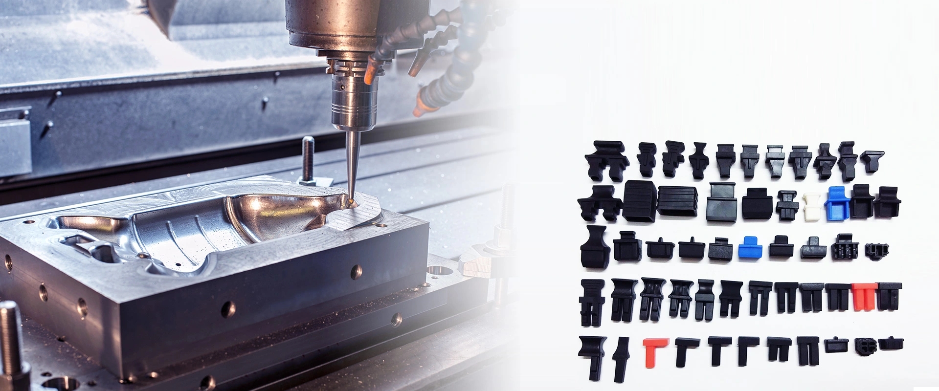
Mechanical Specifications
All modules share identical housing dimensions and employ a bail-style pull tab for unlatching. Contact pads adopt a three-stage sequential mating sequence: ground first, power second, signal last. Host cages are available in 1×1 or n×1 configurations, configurable with integrated heatsinks and EMI springs. Spring-type heatsink clips are recommended to supply a minimum 5 N downward clamping force. Unused port cutouts shall be fitted with dust/EMI blanking covers.
Force specifications: maximum insertion force ≤40 N, maximum extraction force ≤30 N, minimum latch retention ≥90 N and minimum cage retention ≥114 N. Durability is specified as 50 mating cycles for modules and 100 cycles for connectors and cages.
Thermal Management
Three case temperature grades are defined: commercial (0~70 °C), extended industrial (-5~85 °C) and full industrial (-40~85 °C). The QSFP footprint enables side-by-side or back-to-back mounting of up to 16 transceivers within a single 1U rack unit.
Optical Interface
An MPO‑12 receptacle complying with IEC 61754‑7 is deployed with alignment key positioned on the top side. Fiber numbering runs from 12 down to 1 left to right. The four leftmost fibers (12, 11, 10, 9) serve as transmit paths mapped to Tx1~Tx4; the four rightmost fibers (4, 3, 2, 1) function as receive paths corresponding to Rx4~Rx1. The middle four fibers (5 through 8) are physically present but electrically unused.
Management Interface
Management relies on a 2-wire serial bus (I²C-compatible) with fixed slave address A0h. Multiple modules can share a single bus via individual ModSelL selection lines. Register space is split into low page (128 bytes for real-time monitoring, status flags and control registers) and high page: address 00h = read-only ID area, 01h = application selection table, 02h = user-writable EEPROM, 03h = alarm/warning threshold & mask registers. Digital Diagnostic Monitoring (DDM) is supported for case temperature, supply voltage, laser bias current and received optical power with configurable warning and alarm thresholds.
ESD Requirements
All module pins withstand 500 V HBM ESD. When installed inside grounded host cages, assemblies shall comply with EN61000‑4‑2: 8 kV contact discharge and 15 kV air discharge.
Summary
This foundational standard underpins all subsequent high-speed generations including QSFP+ and QSFP-DD specifications.
快速链接
如有任何疑问,请通过电子邮件或Skype联系我们,我们会尽快回复您。
e-mail:sw@2011sw.com
Skype:s13356471172
微信:13356471172